
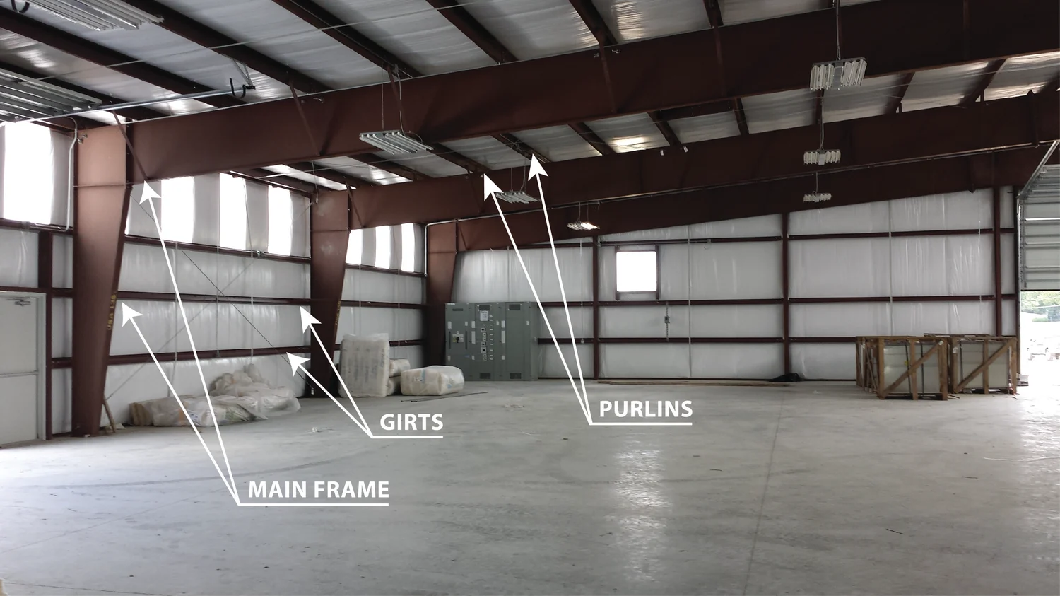
Pre-Engineered Buildings (PEBs) are designed as connected systems where every single part has a specific, calculated job — nothing is just added by default. While the main steel frame carries the biggest structural loads, Purlins and Girts in PEB Structures play an equally important role in supporting the roof and wall systems, and a design mistake at this smaller level tends to show up faster and more visibly than a mistake in the main frame.
Purlins support the roof panels; girts support the wall cladding. Together, they make up the PEB Secondary Structural Members that connect the outer shell of the building to the main frame — and designing them properly isn’t just a small rounding step done after the main structure is finalized. Spacing that’s even a little bit off shows up as sagging panels, water pooling, or fasteners wearing out early, well before the building is supposed to reach the end of its working life. This guide explains what purlins and girts are, the Role of Purlins in PEB Buildings, the Function of Girts in Steel Structures, and the spacing, sizing, and connection choices that decide how well they actually perform.
Purlins and girts are smaller structural pieces used in steel buildings — called “secondary” not because they’re less important, but because they don’t carry the building’s main load straight down to the foundation. That difference matters both for how they’re designed and for where a problem shows up first.
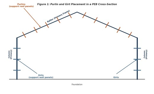
Purlins are horizontal pieces placed along the slope of the roof, running across the rafters. They support the roofing system and pass roof loads — the weight of materials, everyday use, wind, and snow where relevant — over to the main frames. Girts are horizontal pieces installed along the building’s walls, running between the columns. They support the wall panels and pass wind pressure and suction from the cladding back to the main structural frame.
The diagram below shows how each is positioned relative to the primary frame in a typical PEB cross-section.
The Role of Purlins in PEB Buildings goes well beyond just holding roof sheets in place — they’re an active part of how loads move through the building, and treating them as a minor detail is a common cause of avoidable roof problems.
The Function of Girts in Steel Structures is mainly about supporting the building’s wall shell — but because walls face wind pressure from both directions (pushing in and pulling out), girt design has a detail that roof purlin design usually doesn’t need to deal with.
Here’s a practical example: a warehouse wall facing storm winds on a coastal site will usually need closer girt spacing or a heavier piece than an identical wall on the sheltered side of the same building — treating all four sides of the building the same way ignores a real, calculable difference in wind load.
Purlins and girts are classed as PEB Secondary Structural Members because they connect the building’s outer shell to the main structural framework, rather than carrying the load straight down to the foundation themselves. The simplified path the load takes looks like this:
Secondary framing systems commonly use Cee and Zee-shaped steel members to span between primary frames and support roof and wall panels. Metal Sales provides additional information on secondary framing and purlin and girt applications.
Different purlin shapes are used depending on the structural requirements and what the manufacturer offers — the choice isn’t just about looks, it affects how much load the piece can carry, how it connects, and the cost.
Z-shaped, cold-formed pieces are the most widely used shape in PEB projects. Their shape lets them overlap at supports (called “lapping”), which improves how the load carries continuously across spans and increases load capacity compared to a simple, single-span C-shaped piece of the same size — this is a big part of why Z-shaped pieces are so commonly used for longer roof spans.
For additional technical information on Zed and Cee steel purlin profiles and their span applications, see LYSAGHT steel purlins and girts.
C-shaped pieces are used for particular framing situations and smaller support needs — commonly at the ends of the building, at the eaves, or over shorter spans where the overlapping advantage of Z-shaped pieces isn’t needed.
Built-up or specially fabricated pieces are used where the required strength or shape needs something beyond a standard cold-formed profile — for instance, at heavier point loads from hanging equipment, where a standard Z or C shaped piece wouldn’t have enough capacity.
The choice of purlin type should always be based on engineering calculations and the specific needs of the project — not simply on whichever shape a particular manufacturer happens to have in stock.
Common girt options include Z-shaped girts, C-shaped girts, built-up steel pieces, and project-specific cold-formed pieces. The right choice depends on wall height, frame spacing, the type of cladding, wind loads, connection requirements, and the applicable design standards — the same basic engineering logic as choosing purlins, just applied to wall loads instead of roof loads.
Purlin Spacing and Design Guidelines matter because the spacing directly affects how well the roof system performs — and getting this number right involves a real trade-off, not one single “correct” answer that works everywhere.
Purlin spacing is worked out through structural design, taking into account the roof panel’s specifications, roof loading, wind loads, snow loads where relevant, the building’s span, frame spacing, the purlin piece’s capacity, how much bending is allowed, roofing requirements, connection details, and the applicable codes and standards.
Purlin spacing and secondary-framing design should therefore be determined from the applicable structural requirements rather than from a fixed spacing rule. For further technical background, see GlobalSpec’s reference on secondary framing, girts and purlins.
The trade-off works in both directions: if purlins are spaced too far apart, roofing panels have to handle more structural demand and bend more — possibly beyond what the panel maker rates it for, leading to water pooling, visible waviness (called “oil-canning”), or in extreme cases the panel failing under load. If the spacing is unnecessarily close together, steel use and the labour needed for making and installing it goes up without any real benefit in performance. For instance, tightening purlin spacing from 2.0m to 1.5m across a large roof can meaningfully increase the amount of steel used and the number of connections needed — a cost that’s only worth it if the roofing panel or loading conditions actually require it, not something applied everywhere just as an extra safety margin.
Girt spacing is affected by what the wall system needs, including the type of wall panel, wind pressure and suction, wall height, the building’s location, frame spacing, cladding capacity, bending limits, openings, connection design, and applicable standards.
Just like with purlins, girt spacing should be checked against the specific wind zone the project is in — a building in a high-wind coastal zone genuinely needs closer girt spacing or heavier pieces than the same wall height in a low-wind inland location, and using one standard spacing across every site condition either under-designs the exposed building or overspends on the sheltered one.
Purlin and Girt Sizes and Specifications change from project to project — there is no single standard size that works for every PEB, no matter how often generic size charts are treated as a shortcut.
The right size depends on the building’s dimensions, the loading conditions, the roofing and cladding systems, the structural design, and the environmental conditions. Because of this, purlin and girt sizes should be confirmed through engineering calculations specific to the project, rather than picked purely from a generic size chart — a chart can be a useful starting point, but it isn’t a substitute for checking the actual loads on the actual project.
Purlins and girts are usually connected to the main frame using connection plates, cleats, bolts, or other engineered fittings. Connection design needs to take into account the loads being applied, the piece’s capacity, bolt requirements, connection shape, how it will be installed, structural movement, and the applicable design standards.
Connections deserve more attention than their small size might suggest: a purlin or girt is only as effective as the connection passing its load onward, and an under-designed cleat or bolt pattern can actually become the real point of failure, even when the piece itself was sized correctly.
Incorrectly designed or poorly installed secondary members affect how well the building’s outer shell performs in ways that are usually visible well before they become a serious structural issue — which is exactly why it’s worth getting them right the first time, rather than treating them as an easy place to cut costs.
Proper design and manufacturing make sure purlins and girts keep working well throughout the building’s whole working life, instead of becoming the first thing that needs fixing after handover.
During PEB assembly, secondary pieces are installed following a set order:
Skipping the alignment check in step 4 is a common shortcut taken when a schedule is tight — and it’s also the step most likely to cause a visibly wavy roof or wall line once cladding goes on top of secondary framing that isn’t properly lined up.
Properly designed secondary framing gives benefits that add up across the whole project, rather than just showing up as one single cost saving.
Designing secondary members has increasingly moved toward software-assisted calculation — structural design tools can now size purlins and girts directly from the governing load combinations, check bending limits automatically, and work out the best spacing across an entire roof or wall in a fraction of the time manual calculation would take. More and more, AI-assisted detailing tools are being added on top of this to suggest ideal spacing patterns and flag possible clashes with accessories like skylights or louvers before the fabrication drawings are finalized.
This is a genuine efficiency gain, but it doesn’t remove the need for an engineer to check what the software is actually optimizing for. A spacing-optimization tool will reliably reduce the amount of steel used within the load information it’s given — but it won’t independently notice that a wind-load assumption was pulled from the wrong exposure category, or flag that tighter spacing is needed near a roof-mounted equipment platform the model didn’t fully account for. The projects that get the most value from these tools keep an experienced structural engineer reviewing the load inputs and the final spacing output, rather than treating an automatically generated purlin schedule as final just because it passed a software check.
| Feature | Purlins | Girts |
|---|---|---|
| Primary location | Roof, along the slope of the rafters | Walls, along the height of the columns |
| Main purpose | Support roof panels and intermediate roofing loads | Support wall panels and cladding alignment |
| Load transferred | Roof loads (dead, live, wind, snow) to primary frame | Wind pressure and suction from cladding to primary frame |
| Common profiles | Z-section, C-section, built-up sections | Z-section, C-section, built-up sections |
| Key design driver | Roof loads, wind uplift, roofing panel span capacity | Wind pressure/suction, wall height, cladding capacity |
| Structural category | Secondary member | Secondary member |
Purlins and Girts in PEB Structures are essential secondary framing parts that connect the building’s outer shell to the main steel structure. Purlins mainly support the roofing system, while girts support the wall cladding and help pass wall loads back to the main frames.
Understanding What Are Purlins and Girts, the Role of Purlins in PEB Buildings, and the Function of Girts in Steel Structures helps project owners, engineers, contractors, and building users make better decisions during PEB planning and construction. Purlin spacing, girt spacing, piece sizes, specifications, connections, and bracing should all be worked out through engineering specific to the project, rather than generic assumptions. When these parts are properly designed and manufactured, they contribute to efficient material use, reliable cladding support, and overall structural performance throughout the building’s working life.
Our Projects
Hyundai Glovis India

JSW Steel Ltd.

John Deere

SANY Heavy Industries

Hyundai Mobis

Asahi India Glass Ltd.

General FAQs
Purlins are secondary members on the roof that support roofing panels and transfer roof loads to the primary frame, while girts serve the same function on the walls — supporting wall panels and transferring wind pressure and suction back to the primary structure.
Spacing depends on roof panel span capacity, wind and snow loads, building span, frame spacing, and deflection limits — all of which vary by project, so spacing has to be calculated for each building rather than copied from a previous one.
Roofing panels can exceed their rated span capacity, leading to excessive deflection, water ponding, visible waviness (oil-canning), and in severe cases, panel failure under load.
Z-purlins can be lapped at supports, which increases continuity across spans and improves load capacity compared to a single-span C-section of similar size — making them more efficient for longer roof spans.
Often yes — walls facing prevailing wind or a more exposed site orientation can experience higher wind pressure and suction than sheltered walls, which may require tighter girt spacing or heavier sections on that specific elevation.
Generic charts are useful as a reference point, but final sizes should always be confirmed through project-specific engineering calculations, since building dimensions, loading conditions, and environmental factors vary from project to project.
Need Help?
Download Our Company Profile
Please fill in the form below to receive the brochure.
This will close in 0 seconds
Email us with any questions or inquiries.